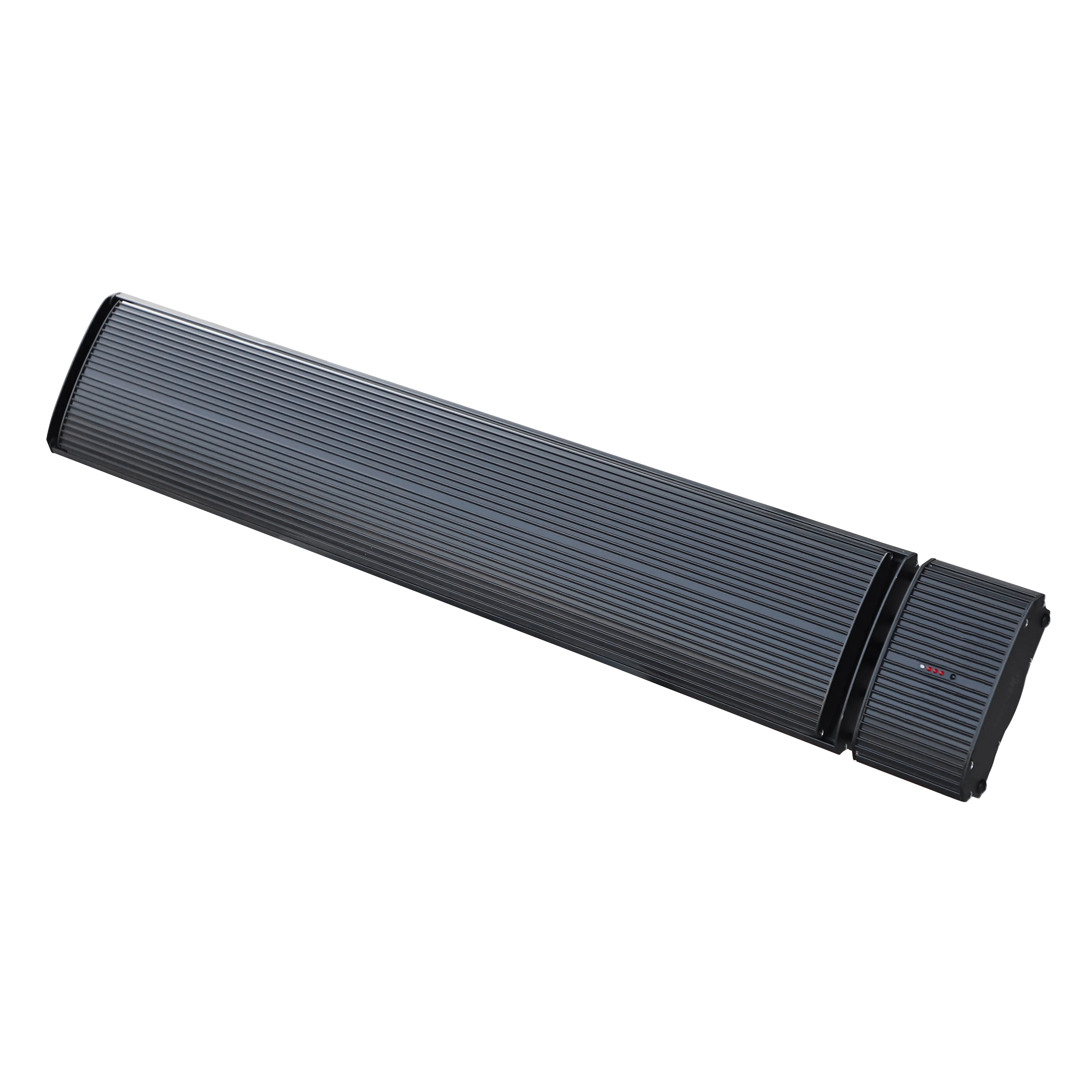
Product Gallery
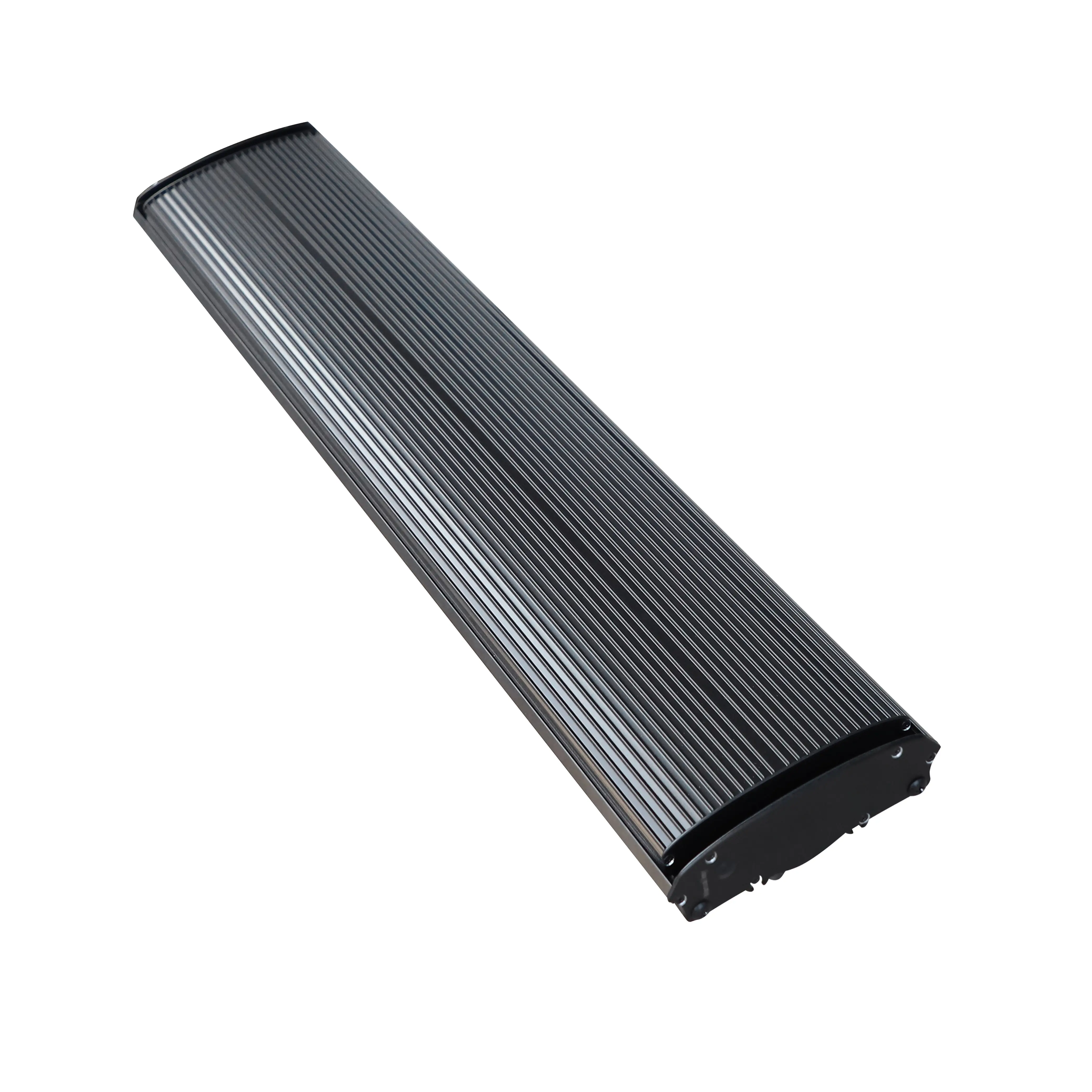
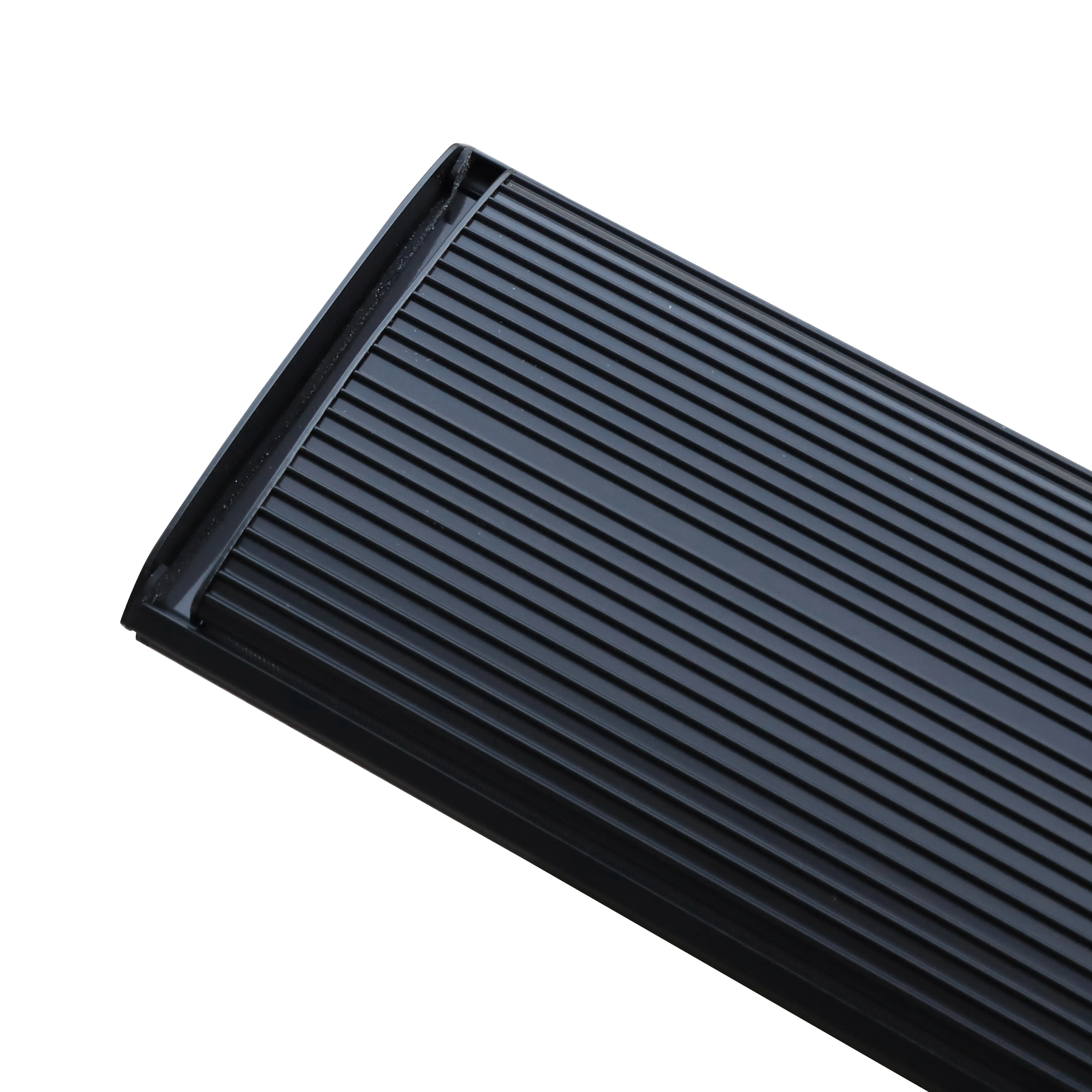
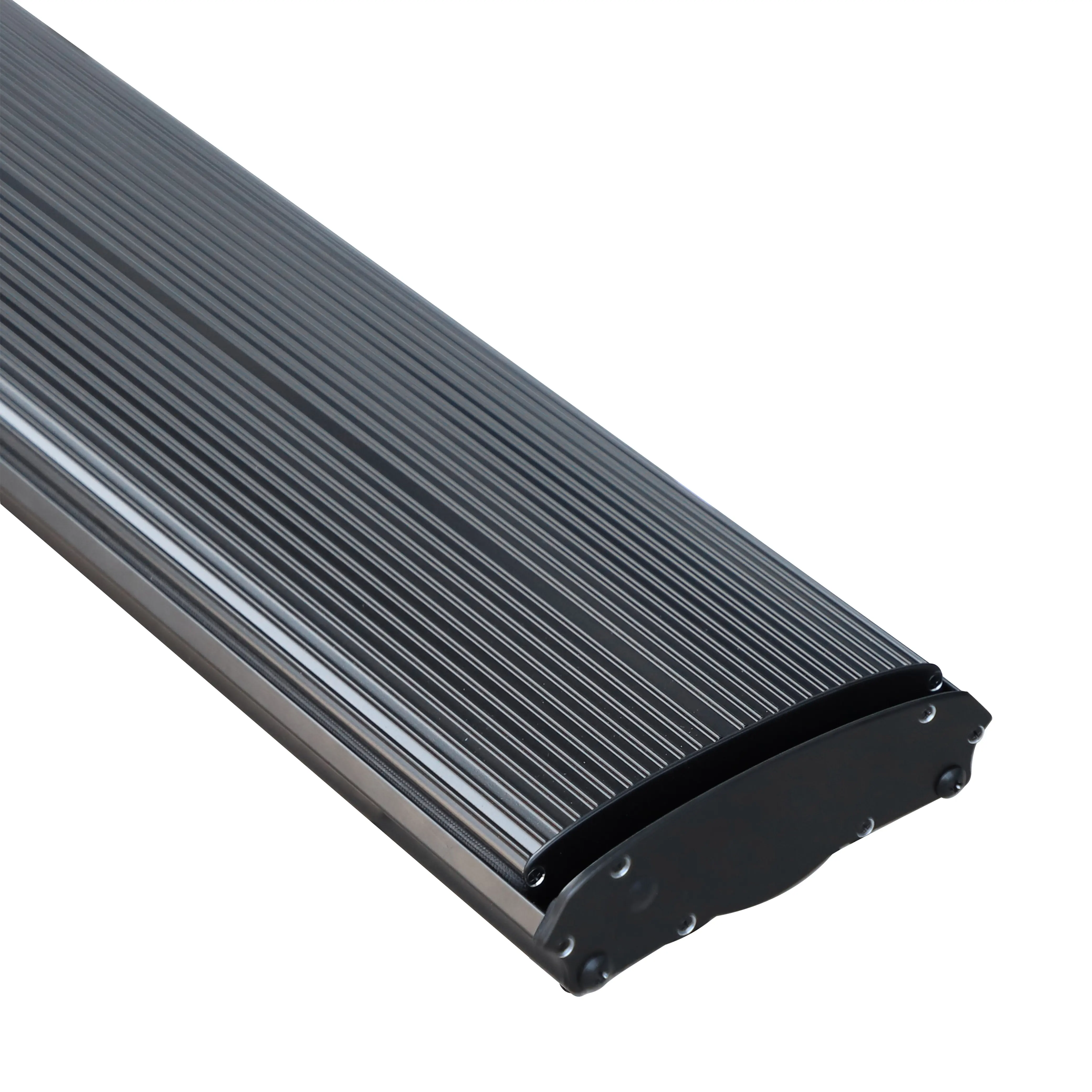
This user manual applies to JH Infrared Heater 13 Series (13A/13B) and 14 Series (14A/14B) series. These far-infrared radiant heaters use advanced aluminum panels with a special coating to deliver efficient, comfortable, and clean heating. Please read all instructions carefully before installation and use.
No wind, no light, no odor. Indoor air stays clean without floating dust.
High heat generation with excellent distribution. Uses less energy than traditional heating methods.
Indoor temperature can be freely adjusted, not limited by heating season.
Infrared radiant heat promotes microcirculation, adjusts the nervous system, and boosts metabolism.
| Model No. | Power (W) | Rated Current (A) | Voltage (V) | Cable length (mm) |
|---|---|---|---|---|
| JH-NR10-13A/B | 1000 | 4.3 | 220–240 | 2000 |
| JH-NR18-13A/B | 1800 | 7.8 | 220–240 | 2000 |
| JH-NR24-13A/B | 2400 | 10.4 | 220–240 | 2000 |
| JH-NR32-13A/B | 3200 | 13.9 | 220–240 | 500 |
| JH-NR40-13A | 4000 | 5.8 | 380–415 | 500 |
| Model No. | Power (W) | Rated Current (A) | Voltage (V) | Cable length (mm) |
|---|---|---|---|---|
| JH-NR10-14A/B | 1000 | 4.3 | 220–240 | 2000 |
| JH-NR18-14A/B | 1800 | 7.8 | 220–240 | 2000 |
| JH-NR24-14A/B | 2400 | 10.4 | 220–240 | 2000 |
| JH-NR32-14A/B | 3200 | 13.9 | 220–240 | 500 |
| JH-NR40-14A | 4000 | 5.8 | 380–415 | 500 |
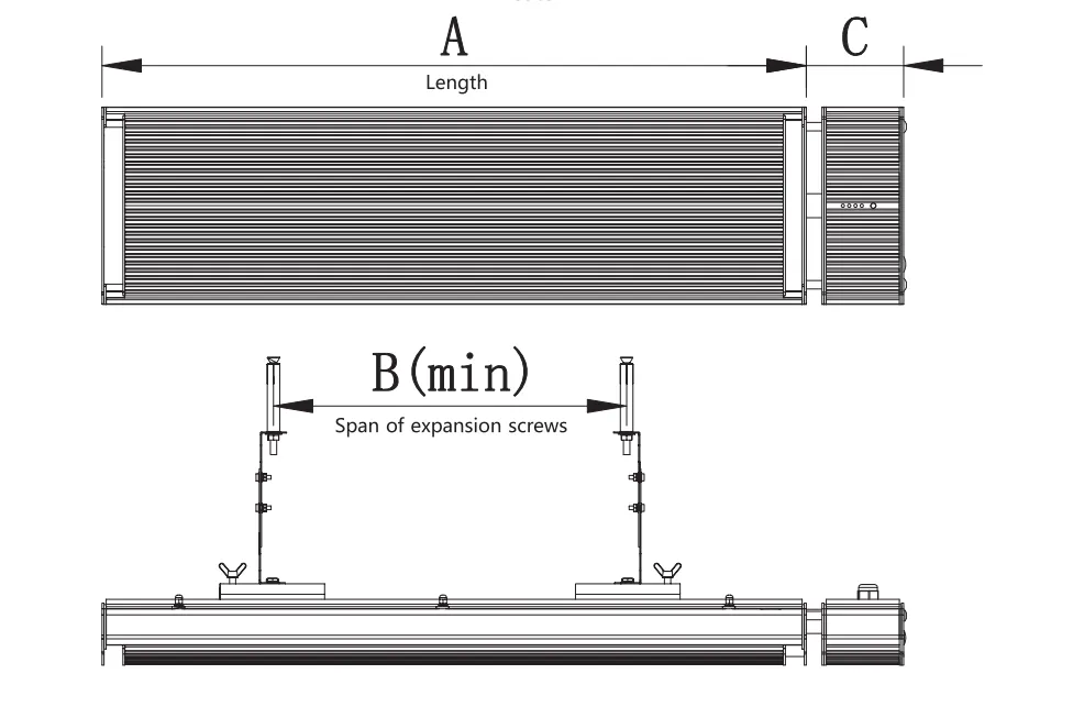
| Model No. | Dimension A | Dimension B | Dimension C |
|---|---|---|---|
| JH-NR10-13A/B | 600mm | 200mm | 95mm |
| JH-NR18-13A/B | 1000mm | 700mm | 95mm |
| JH-NR24-13A/B | 1500mm | 1200mm | 95mm |
| JH-NR32-13A/B | 2000mm | 1700mm | 95mm |
| JH-NR40-13A | 2000mm | 1700mm | / |
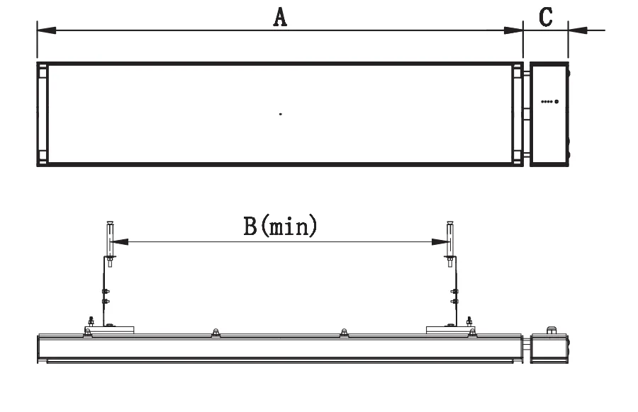
| Model No. | Dimension A | Dimension B | Dimension C |
|---|---|---|---|
| JH-NR10-14A/B | 600mm | 200mm | 95mm |
| JH-NR18-14A/B | 1000mm | 700mm | 95mm |
| JH-NR24-14A/B | 1500mm | 1200mm | 95mm |
| JH-NR32-14A/B | 2000mm | 1700mm | 95mm |
| JH-NR40-14A | 2000mm | 1700mm | / |
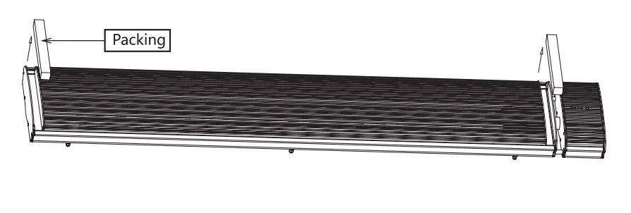
Remove packing from both ends of the heater.
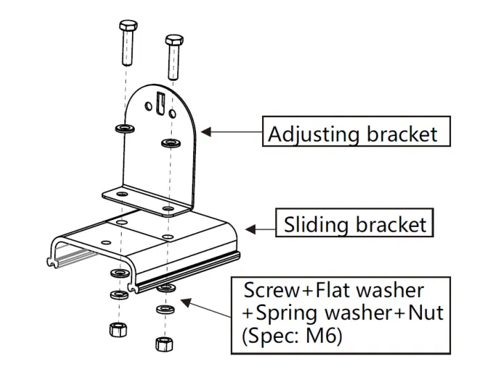
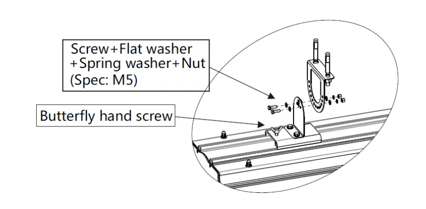
Connect adjusting bracket to sliding bracket.
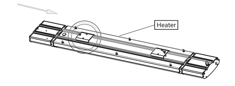
Install the sliding bracket and heater as indicated by the arrows.
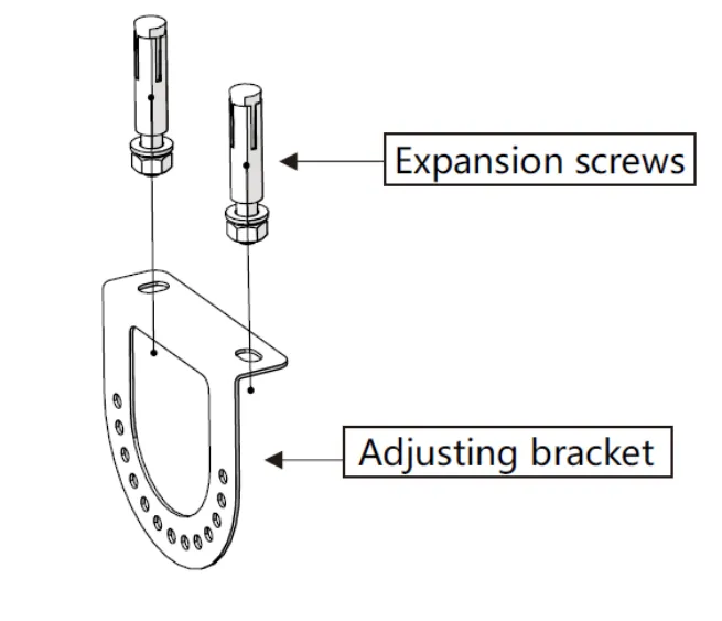
Fix the adjusting bracket to the wall using expansion screws.
Install both adjusting brackets and tighten the butterfly hand screws firmly.
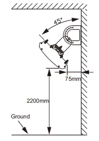
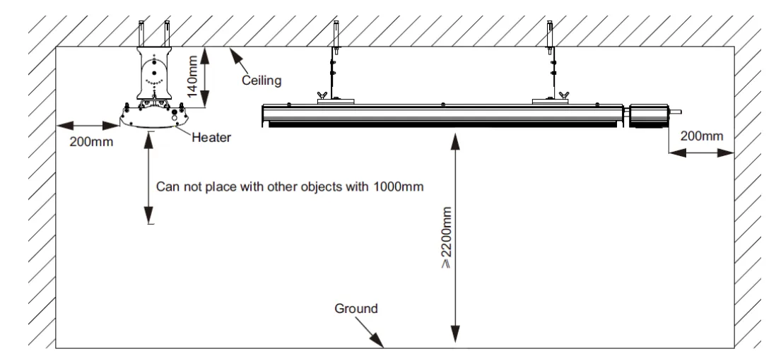
The heater can be installed on the wall or ceiling. Ensure the installation angle is adjusted correctly for optimal heating coverage.
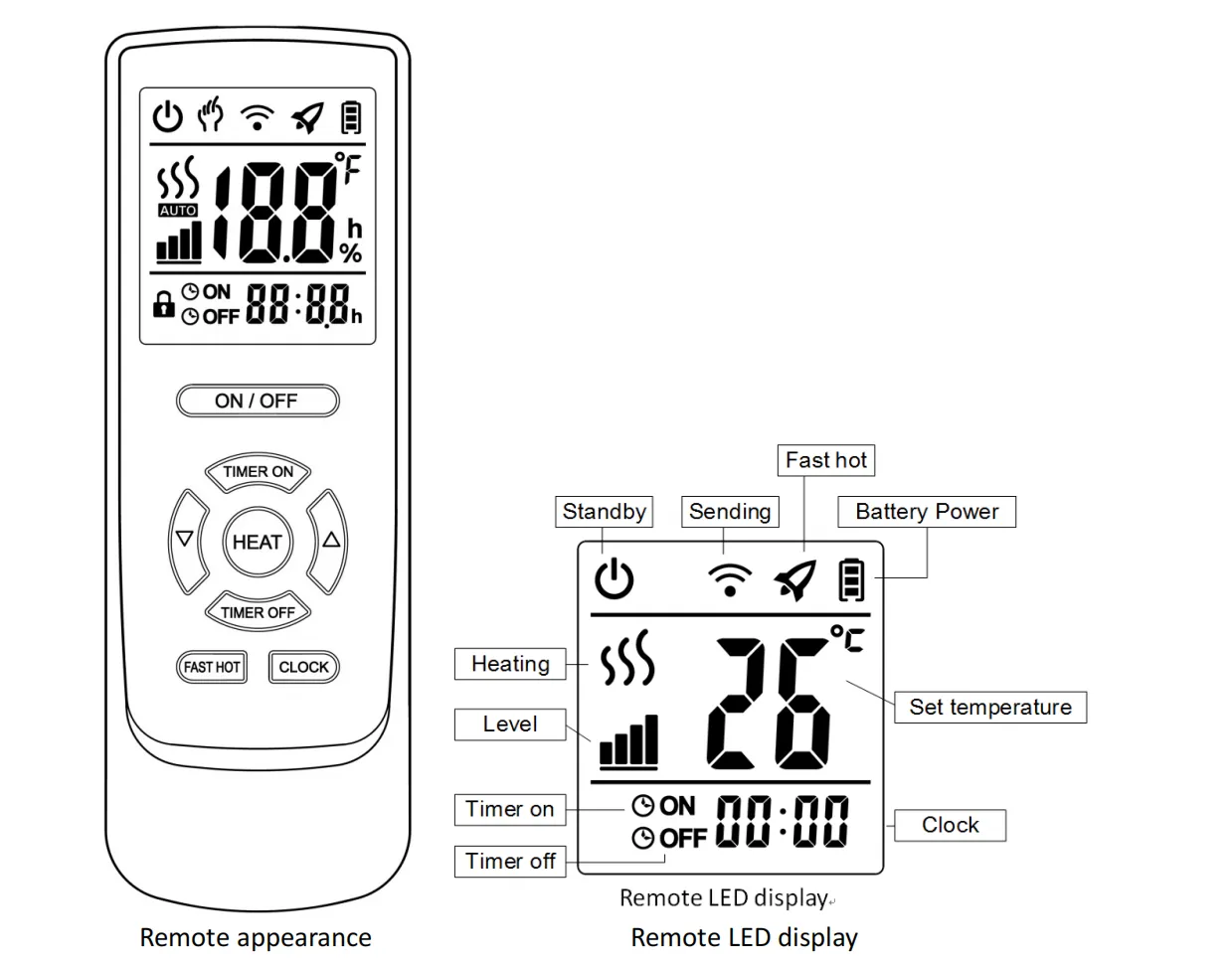
Press the ON/OFF button to turn the heater on or off.
Press Clock → use ▲/▼ to adjust hours → press Clock → adjust minutes → press Clock → adjust seconds → press Clock to confirm.
Press the Level button while the heater is on to adjust the power level (4 levels: 25% / 50% / 75% / 100%).
Press Fast Heat button to run the heater at full power for rapid heating.
Press Timer ON → set hours with ▲/▼ → press Timer ON → set minutes → press Timer ON to confirm.
Press Timer OFF → set hours with ▲/▼ → press Timer OFF → set minutes → press Timer OFF to confirm.
The heater is equipped with LED indicator lights to show the current power level.
The timer function allows you to set automatic ON and OFF times. This is useful for pre-heating a room before occupancy or automatically turning off the heater at night.
Perform the following inspection after installation and before each use to ensure safe operation.
| Inspection Item | Method | Standard |
|---|---|---|
| Grounding continuity | Use multimeter to test resistance between ground terminal and heater body | Resistance < 0.1 Ω |
| Insulation resistance | Use 500V megohmmeter to test live-to-ground resistance | Resistance ≥ 2 MΩ |
| Power consumption | Measure with power meter at rated voltage | Within ±10% of rated power |
| Surface temperature | Measure with infrared thermometer after 30 min operation | Within specified range, no overheating |
| Model No. | Dimension (mm) | Package Size (mm) | Net Weight (kg) | Gross Weight (kg) |
|---|---|---|---|---|
| JH-NR10-13A | 600×189×67 | 695×250×145 | 3.7 | 4.8 |
| JH-NR18-13A | 1000×189×67 | 1095×250×145 | 6.2 | 7.4 |
| JH-NR24-13A | 1500×189×67 | 1595×250×145 | 8.8 | 10.6 |
| JH-NR32-13A | 2000×189×67 | 2095×250×145 | 11.4 | 13.4 |
| JH-NR40-13A | 2000×189×67 | 2095×250×145 | 11.4 | 13.4 |
| JH-NR10-13B | 695×189×67 | 790×250×145 | 4.3 | 5.4 |
| JH-NR18-13B | 1095×189×67 | 1190×250×145 | 6.8 | 8.0 |
| JH-NR24-13B | 1595×189×67 | 1690×250×145 | 9.4 | 11.2 |
| JH-NR32-13B | 2095×189×67 | 2190×250×145 | 12.2 | 14.2 |
| Model No. | Dimension (mm) | Package Size (mm) | Net Weight (kg) | Gross Weight (kg) |
|---|---|---|---|---|
| JH-NR10-14A | 600×215×70 | 695×275×140 | 3.6 | 4.8 |
| JH-NR18-14A | 1000×215×70 | 1095×275×140 | 6.1 | 7.5 |
| JH-NR24-14A | 1500×215×70 | 1595×275×140 | 8.8 | 10.8 |
| JH-NR32-14A | 2000×215×70 | 2095×275×140 | 11.6 | 13.8 |
| JH-NR40-14A | 2000×215×70 | 2095×275×140 | 11.6 | 13.8 |
| JH-NR10-14B | 695×215×70 | 790×275×140 | 4.3 | 5.5 |
| JH-NR18-14B | 1095×215×70 | 1190×275×140 | 6.8 | 8.2 |
| JH-NR24-14B | 1595×215×70 | 1690×275×140 | 9.5 | 11.5 |
| JH-NR32-14B | 2095×215×70 | 2190×275×140 | 12.3 | 14.5 |
Due to thermal expansion and contraction, the heater may produce slight noise when turning on or off. This is a normal phenomenon and does not affect performance or safety. If abnormal noise occurs during operation, please cut off power immediately and contact authorized service.